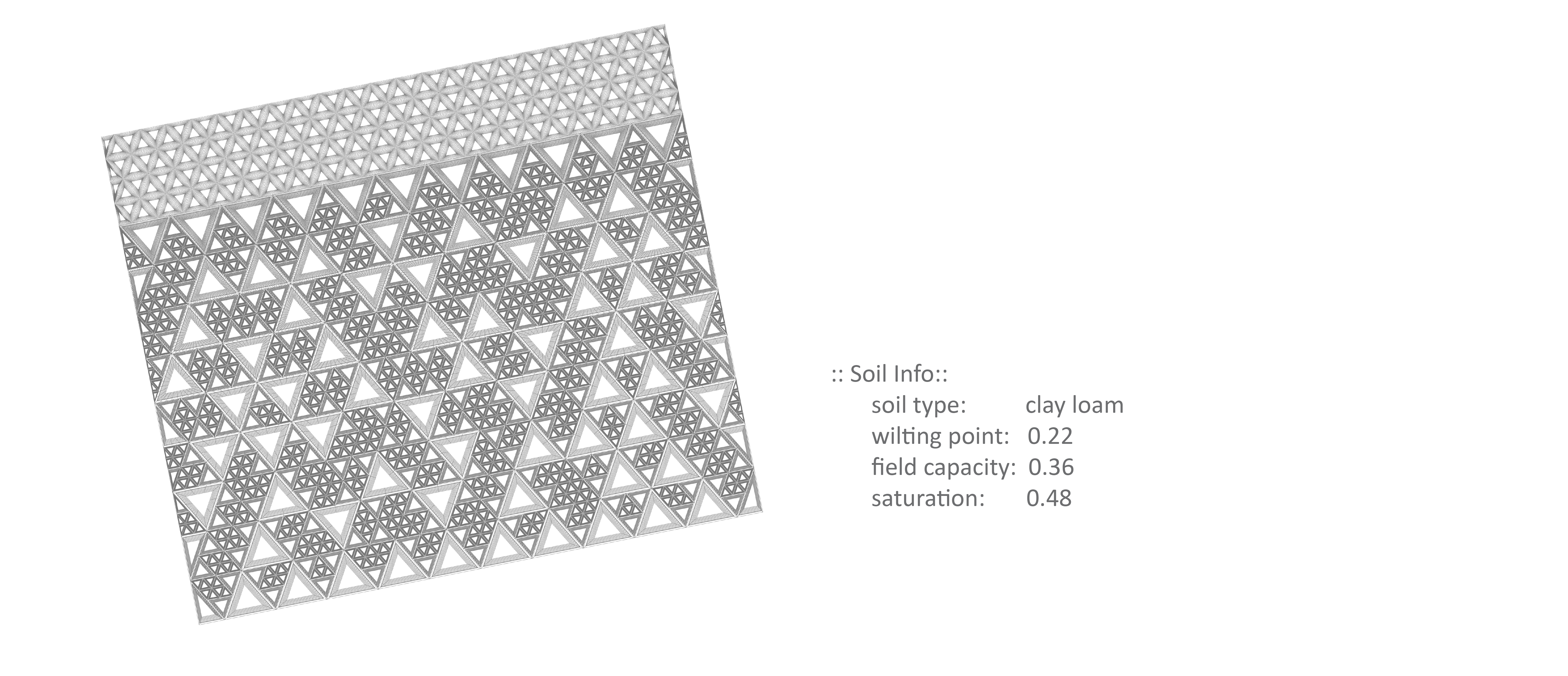
01::Soil
Introduction
The Soil cluster provides a series of components that define the basic characteristics of the soil (content ratio, water, organic matter), that calculate the water holding capacity based on the soil type, and that create parametric diagrams based on these information.
Soil Type
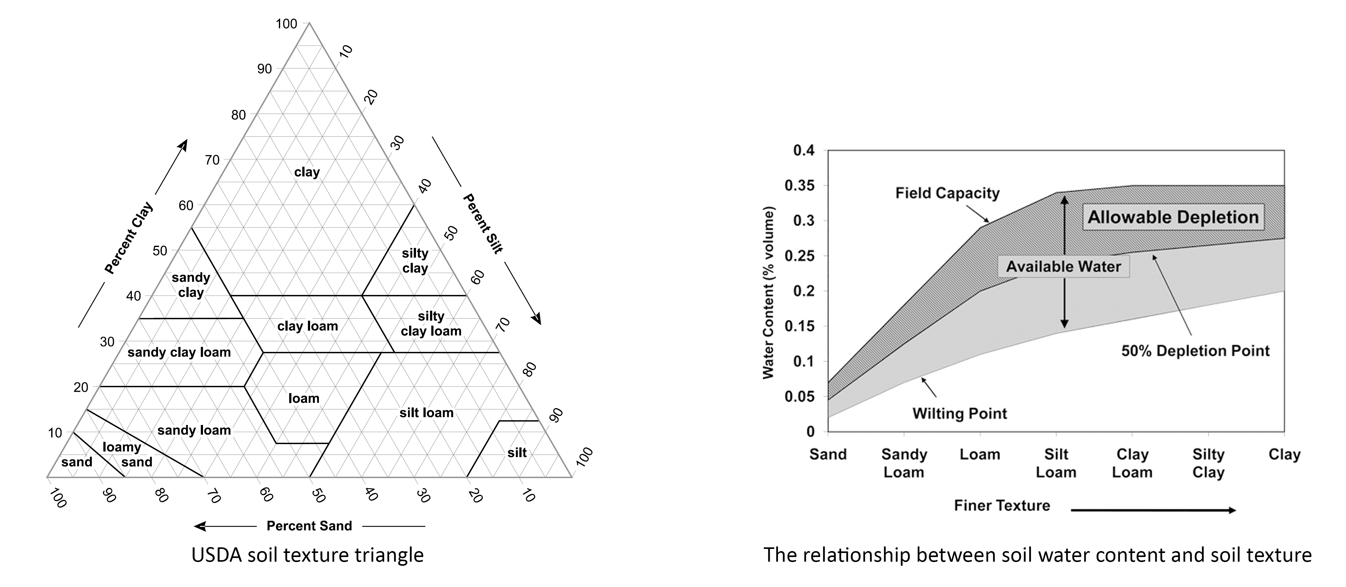
Soil types in BeingAliveLanguage are referenced from USDA soil texture classification system, which differentiates 12 soil types by the ratio of three primary particles: sand, silt and clay. The soil types are summarised in the textural triangle1 on the left.
Beyond the three particles, water, organic matter and air play a role in soil system as well. By specifying the soil type, the possible range of water content in a soil type can be estimated using existing research data, while organic matter content should be measured from field test considering its seasonal and regional variations. The following chart on the right shows available water in various soil types.
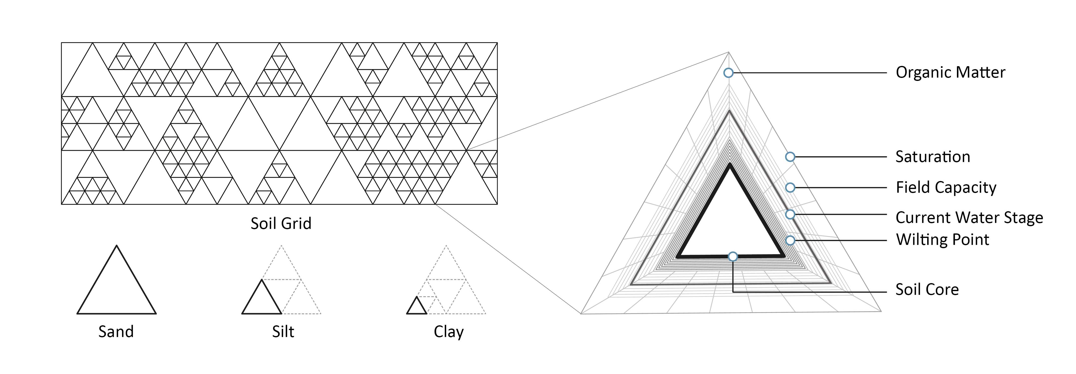
Soil Content Representation
The soil contents are visualized in a unified triangle frame which is deliberately chosen for connection to USDA soil system and the preferable tessellation ability. The three primary particles - sand, silt, and clay - are represented with triangles of three sizes from large to small. Information about water content, including wilting point, current water stage, field capacity and saturation, is shown by triangles between the soil core triangle and outmost layer. The organic matter inside the soil, located at the outmost part of the soil, is illustrated by radial hatching.
Component Usage
Please refer to the following sections for each component from this cluster. Some of the components also generate required information for component usage in the Root and Climate cluster.
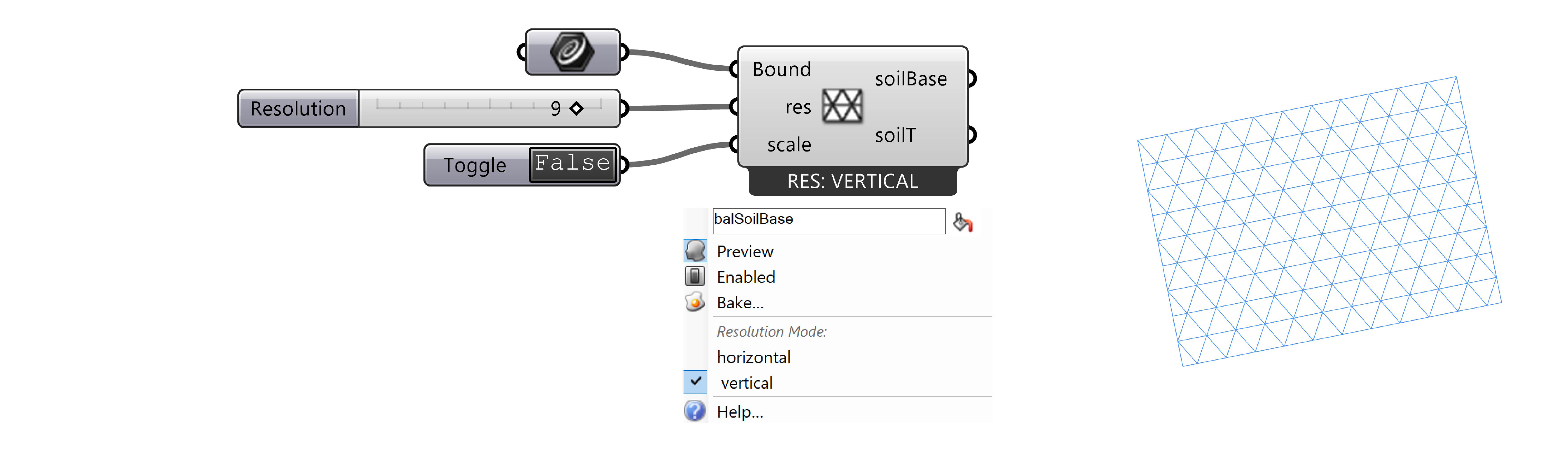
Soil Base
This component creates a triangle grid inside the given solid boundary.
| Parameter | Abbreviation | I/O | Optional | Explanation |
|---|---|---|---|---|
Boundary |
Bound |
No | A rectangular boundary curve of the soil. | |
Resolution |
res |
No | # of vertical division for the soil grid. | |
Scale |
scale |
Yes | If true, the generated grids will be scaled to fill the boundary. | |
Soil Base |
soilBase |
The initiated soil base, containing essential info for the soil/root computing. | ||
Soil Base Grid |
SoilTrid |
Collection of all the curves in the soil grid. |
-
Context Menu: This component provides an additional option in the right-click menu to determine the reference side of the boundary for triangle generation. By selecting the
verticalmode, the triangles will align vertically with the boundary, leaving a gap on the other vertical side if the boundary cannot be exactly divided into regular triangles. Vise versa for thehorizontalmode. To fill this gap, please use theScaleparameter. -
Notes on Scale: The
Scaleparameter allows users to scale the generated triangles and fill the rectangular boundary defined by users. If an irregular boundary is used, the component will not raise an error, but the scaled triangles may not fit within the boundary. After scaling, the triangles will no longer be regular triangles. This is important to consider if the triangles are intended to be used as input for the Root_SoilMap component to generate roots. In such a case, the Root_SoilMap component will raise an error since it needs to follow the vertices of regular triangles to generate roots.
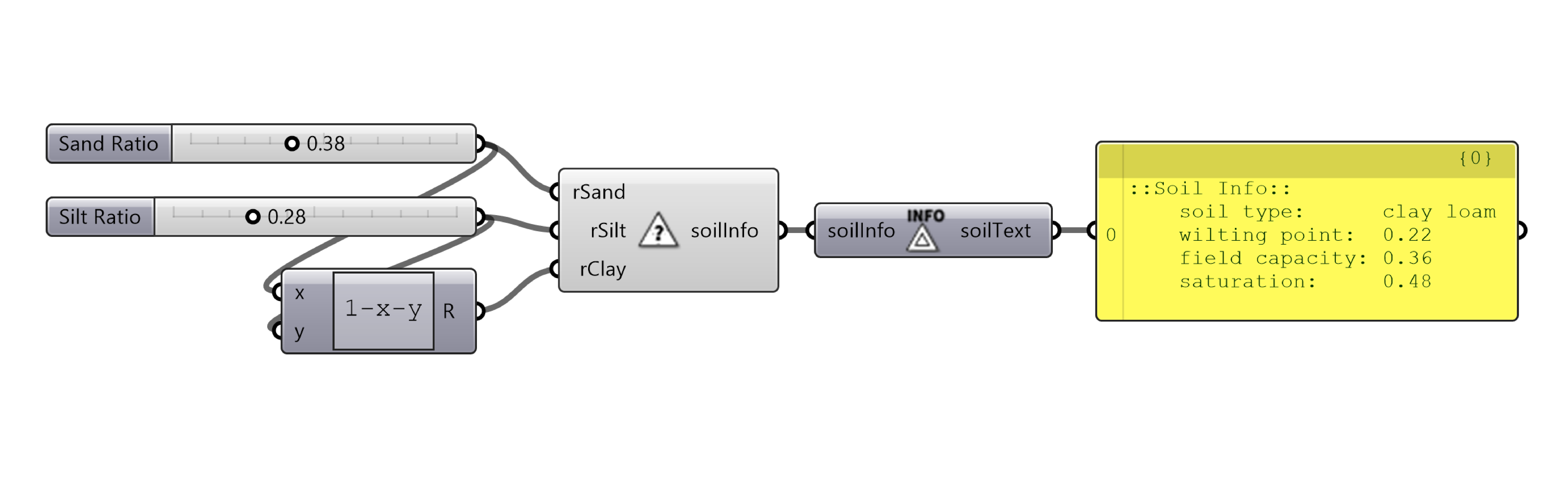
Soil Analysis
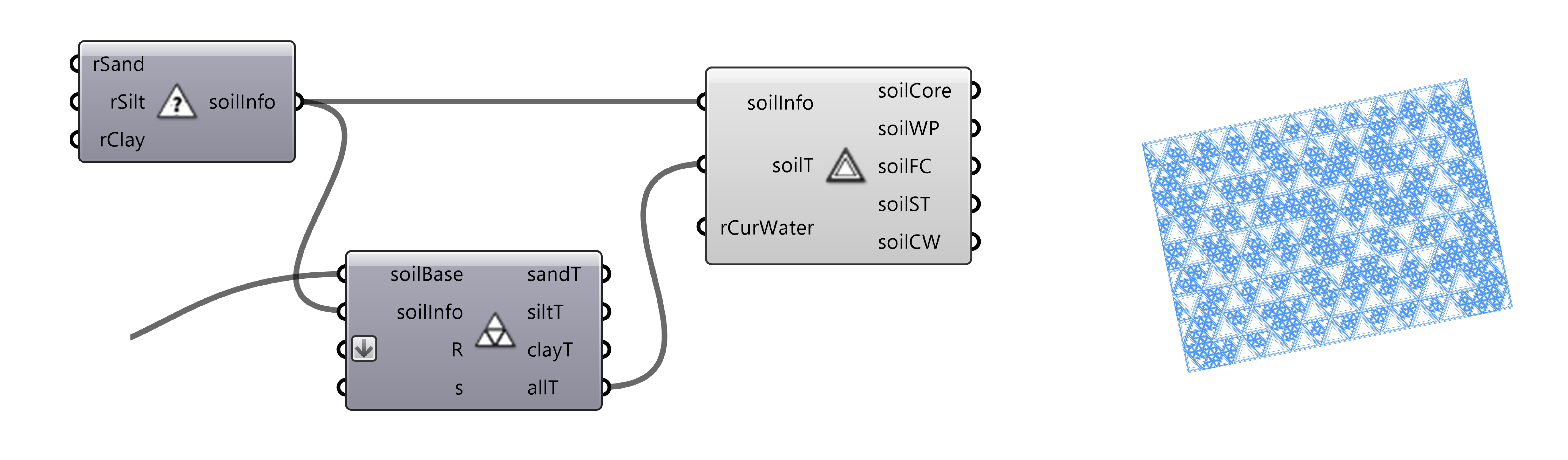
This component defines the soil type and generates information of soil based on the ratio of the three soil contents.
| Parameter | Abbreviation | I/O | Optional | Explanation |
|---|---|---|---|---|
Sand Ratio |
rSand |
No | The ratio [0, 1] of sand content in the soil. |
|
Silt Ratio |
rSilt |
No | The ratio [0, 1] of silt content in the soil. |
|
Clay Ratio |
rClay |
No | The ratio [0, 1] of clay content in the soil. |
|
Soil Info |
soilInfo |
Info about the current soil based on given content ratio. |
General Soil Separates
This component generates a soil map according soil base and soil contents. If rock curves are provided, the rock area will be bypassed.
The component takes a pre-generated soil base (a triangle map) and defined soil information to generate diagrams representing the soil composition. The locations of the different-size triangles are randomly distributed.
Optional rock curves can be added to generate a soil map that avoids the unfavoured area.
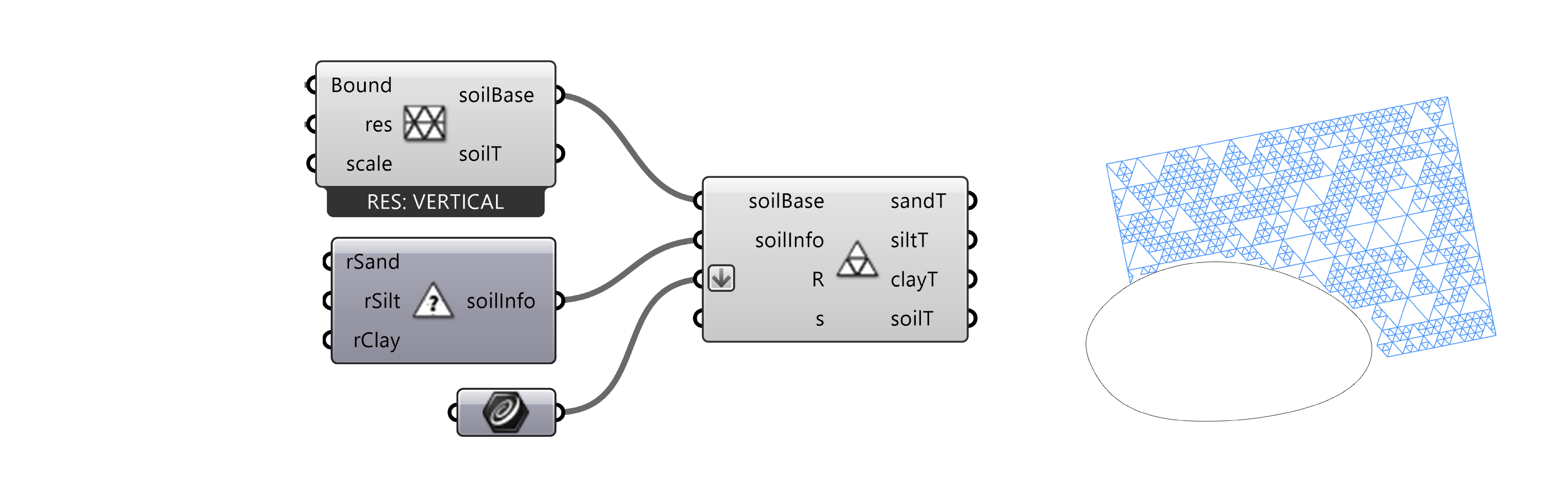
| Parameter | Abbreviation | I/O | Optional | Explanation |
|---|---|---|---|---|
Soil Base |
soilBase |
No | The soil base, using output from the Soil Base component. | |
Soil Info |
soilInfo |
No | The soil info, using optput from the Soil Analysis component. | |
Rocks |
R |
Yes | Curves represendting the rocks in the soil. | |
seed |
s |
Yes | Integer seed for randomize the generated soil pattern. | |
stage |
t |
Yes | Integer stage index [1 - 8] representing the randomness of the soil separates that are gradually changed by the organic matter. | |
Sand Triangle |
sandT |
Sand triangles. | ||
Silt Triangle |
siltT |
Silt triangles. | ||
Clay Triangle |
clayT |
Clay triangles. | ||
All Triangle |
soilT |
All soil triangles. |
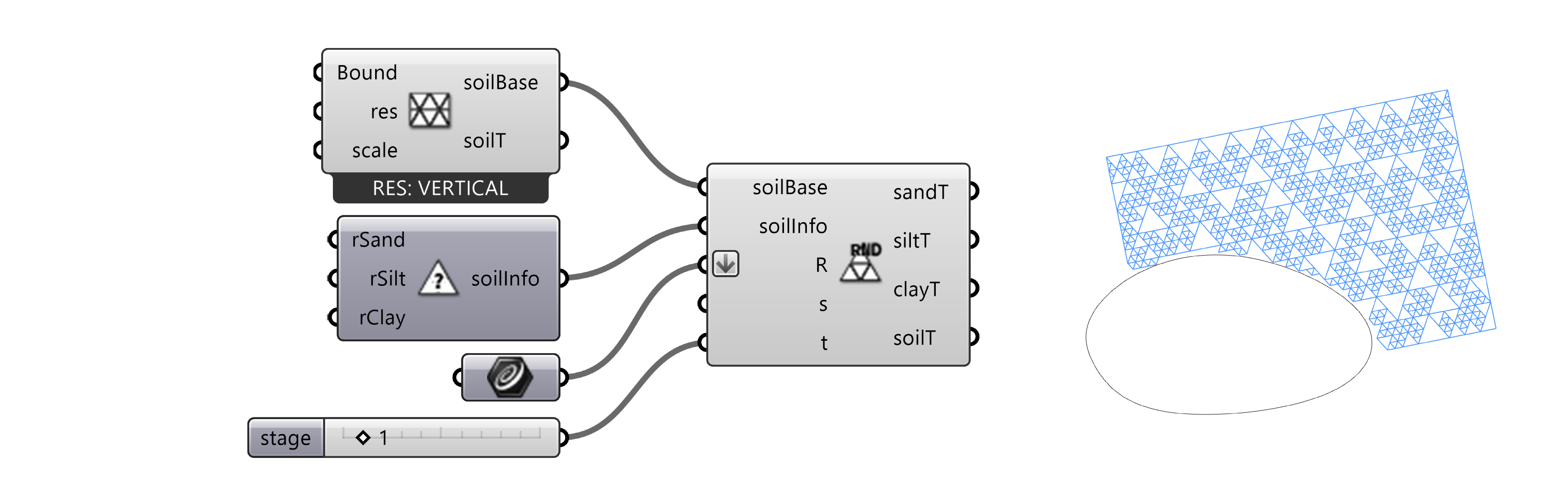
General Soil Separates with Randomness Control
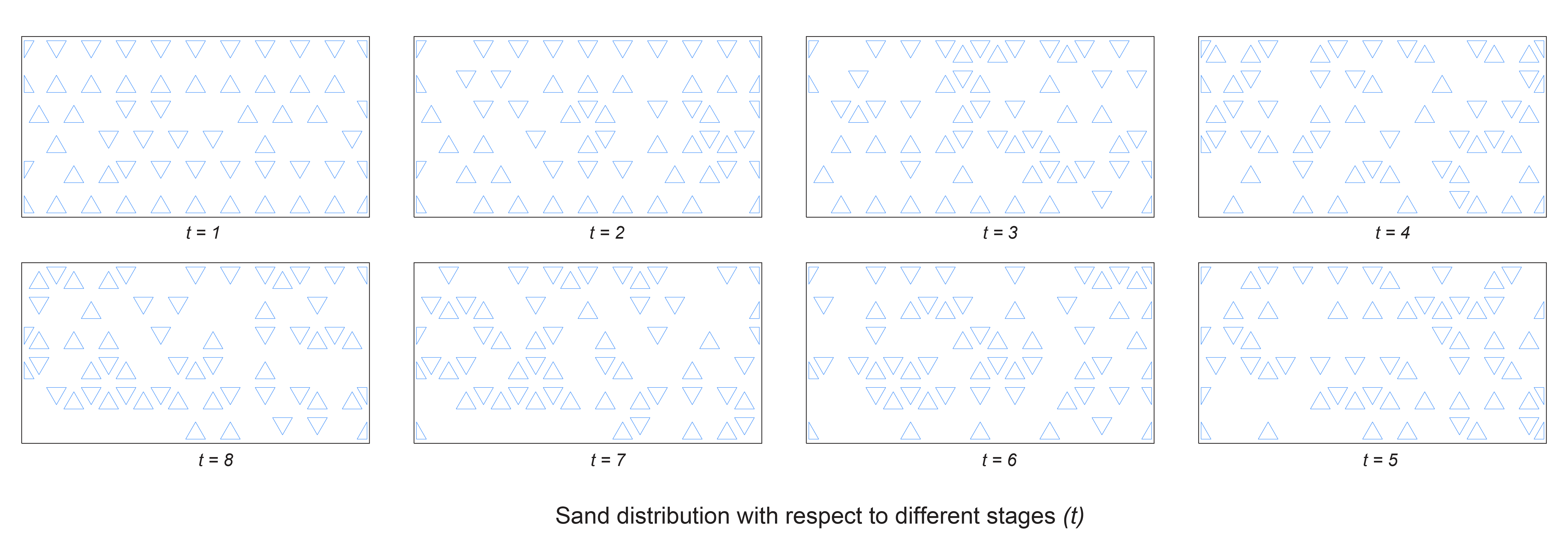
This component offers enhanced control over the randomness of the triangles' distribution. Given that the majority of the parameters align with those found in the General Soil Separates component, we will focus on introducing the additional stage parameter here, which is utilized to regulate the randomness.
This randomness feature is only available on Windows.
| Parameter | Abbreviation | I/O | Optional | Explanation |
|---|---|---|---|---|
stage |
t |
Yes | Integer stage index [1 - 8] representing the randomness of the soil separates that are gradually changed by the organic matter. |
- Randomness: Index 1 indicates a relatively even distribution with a low level of randomness, while index 8 represents highest level of randomness, shown in the following diagram.
- State Preservation: Due to certain technical issues with 'Possion's Disk Sampling with Elimination'2, the state preservation with seed is currently unstable within this component. This instability implies that saving and reopening the file may result in changes of the distribution. (To retain the original distribution, consider internalizing the triangles using a
curveordataparameter within Grasshopper.)
Soil Compaction
This component generates diagram of soil compaction based on given the given compaction area and strength.
Soil compaction refers to 'the process in which a stress applied on soil causes densification as air is displaced from the pores between the soil grains'.3 The dynamics of compaction are influenced by many factors, such as soil water content, texture, and applied stress. Moreover, the severity of compaction diminishes with increasing depth, meaning surface soil tends to be more compacted than the soil at greater depths. This component models such phenomena and use inputs such as soil triangles, compacted depth, and stress strength to generate a corresponding compaction diagram.
More information about soil compaction could be found here.
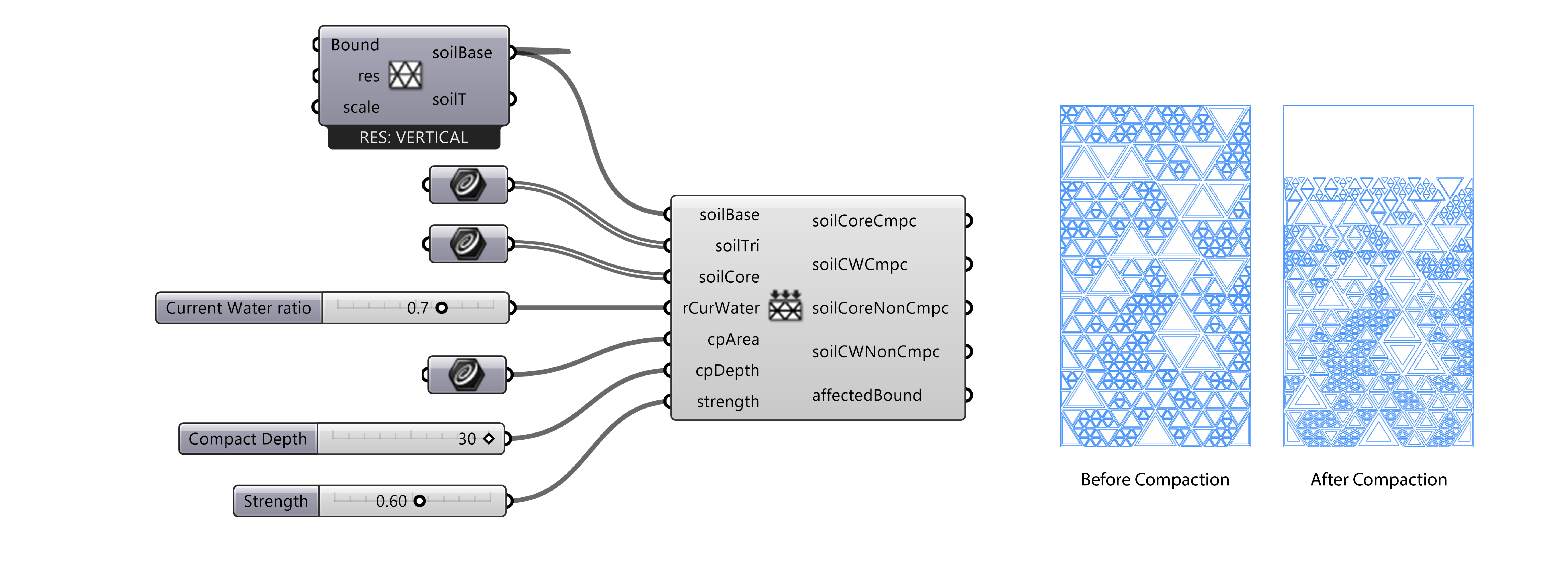
| Parameter | Abbreviation | I/O | Optional | Explanation |
|---|---|---|---|---|
Soil Base |
soilBase |
No | The soil base, using output from the Soil Base component. | |
Soil Triangle |
soilTri |
No | Soil triangles that represents the initial soil separates divsion, using the output parameter soilT from the General Soil Separates component. |
|
Soil Core |
soilCore |
No | Soil core triangles that represents soil separates without any water, using the output parameter soilCore from the Soil Water Visualization component. |
|
Current Water Ratio |
rCurWater |
Yes | The current water ratio [0, 1] in the soil for visualization purposes. |
|
Compact Area |
cpArea |
No | Compaction area near the soil surface. Using lines or curves as the input. | |
Compact Depth |
cpDepth |
No | Compaction Depth, unit associated with Rhino's unit. | |
Strength |
strength |
Yes | Compaction strength, range [0, 1] . |
|
Soil Core Compacted |
soilCoreCmpc |
Soil core separates after compaction. | ||
Soil Current Water Compacted |
soilCWCmpc |
Water content after compaction. | ||
Soil Core Non-Compacted |
soilCoreNonCmpc |
Soil core separates after compaction outside the compaction area. | ||
Soil Current Water Non-Compacted |
soilCWNonCmpc |
Water content after compaction outside the compaction area. | ||
Affected Boundary |
affectedBound |
Boundary of the affected soil after compaction.. |
- Notes on Particle Collision: Since the component does not incorporate built-in collision detection, there is a possibility that particles may overlap with others. This scenario often arises when the
Compact Depthparameter is set to a low value, whileStrengthis set high. In such instances, it is recommended to adjust these values accordingly. \ Another common collision scenario occurs at the boundary between compacted and non-compacted soil, specifically when only a portion of the soil has been compacted. To address this issue, some manual intervention may be required. For example, users could consider separating the boundaries of non-compacted part from the compacted part whening using Soil Base component and the General Soil Separates component to generate soil triangles.
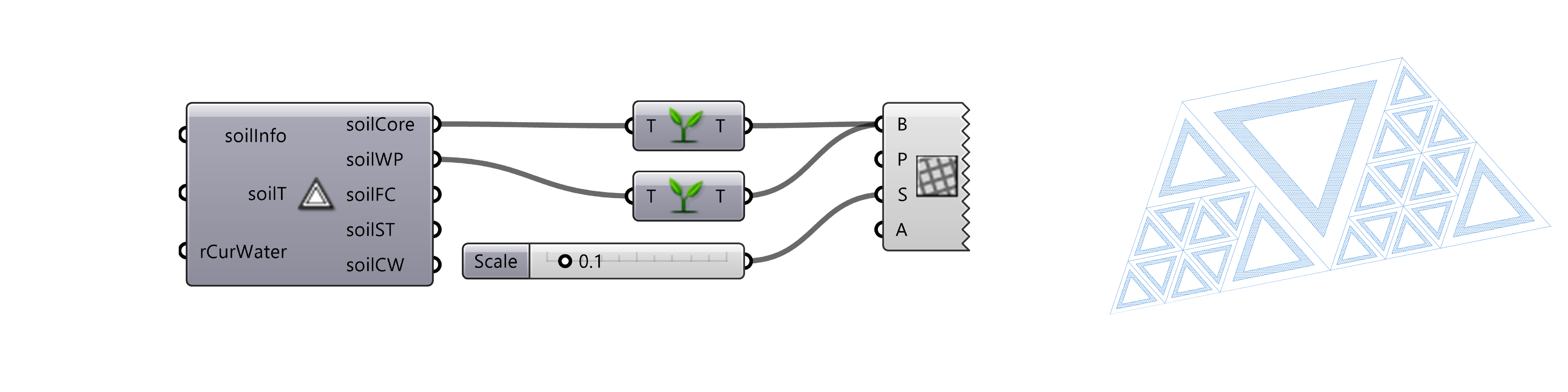
Soil Water Visualization
This component generates a soil diagram with essential water information.
Taking defined soil information and desired soil triangles as inputs, the component generates five group of curves which stand for core triangles, wilting point triangles, field capacity triangles, saturation triangles and current water triangles.
| Parameter | Abbreviation | I/O | Optional | Explanation |
|---|---|---|---|---|
Soil Info |
soilInfo |
No | Info about the current soil based on given content ratio, using output from the Soil Analysis component. | |
Soil Triangle |
soilT |
No | Soil triangles that are used to visualize the water infomation, using output from any output of the soil content from the General Soil Separates component. | |
Current Water Ratio |
rCurWater |
Yes | The current water ratio [0, 1] in the soil for visualization purposes. |
|
Soil Core |
soilCore |
Soil core triangles that represents soil separates without any water, using the output parameter soilCore from the Soil Water Visualization component. |
||
Wilting Point |
soilWP |
Soil wilting point triangles. | ||
Field Capacity |
soilFC |
Soil field capacity triangles. | ||
Saturation |
soilST |
Soil saturation triangles. | ||
Current Water Content |
soilCW |
Soil current water triangles. |
Soil Water Content Hatch
The hatch of different water content could be customized using outputs from Soil Water Visualization component and Pattern Hatch component embedded in Grasshopper. It is highly recommended to graft the triangles before linking to the hatch component, as this can speed up the operation considerably. If colorful pattern is favored, one could also consider creating nurbs surfaces from the triangles and coloring the surfaces.
Soil Organic Matter
To visualize the organic matter inside the soil, we differentiate the interior and surface organic matter:
- interior organic matter: organic matter that exists inside the soil.
- surface organic matter: organic matter that exists on the soil surface.
As in reality, organic matter from the top surface will gradually merge into the soil and increase interior organic matter near the top, users should adjust the density of the two parts so that the visualization delivers the correct information.
Soil Interior Organic Matter
This component generates the diagram of soil interior organic matter for the given soil base map.
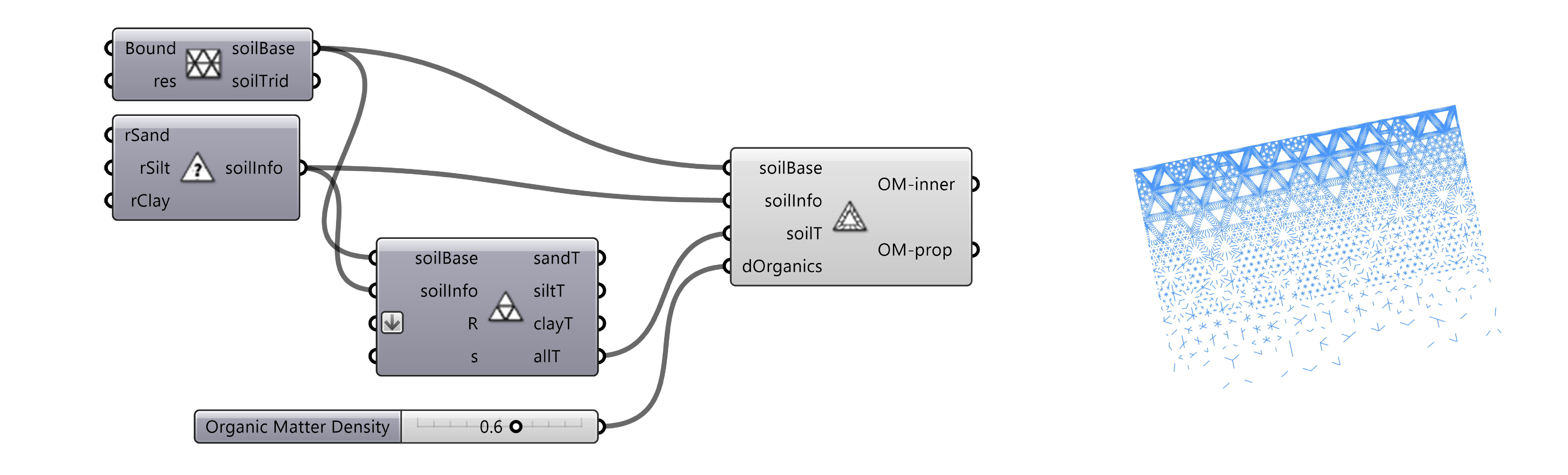
| Parameter | Abbreviation | I/O | Optional | Explanation |
| ------------------------- | ------------ | :---------------: | :------: | -------------------------------------------------------------------------------------------------------------------------- | --- |
| Soil Base | SoilBase | | No | The soil base, using output from the Soil Base component. |
| Soil Info | soilInfo | | No | Info about the current soil based on given content ratio, using output from the Soil Analysis component. | |
| Soil Tri | soilT | | No | Soil triangles, can be any or combined triangles of sand, silt, clay. |
| Organic Matter Density | dOrganics | | Yes | Density of organic matter [0, 1]. |
| Organic Matter Inner | OM-inner | | | Line segments diagram as inner soil organic matter. |
| Organic Matter Property | OM-prop | | | Property of inner organic matter to generate top organic matter. |
Soil Surface Organic Matter
As the diagram of the top surface is not related to the specific distribution of the soil content, organic matter in this realm can be generated independently without the specific information of soil content, we provide two components (dependent-version and independent-version) that work similarly to generate the diagram of the soil's surface organic matter:
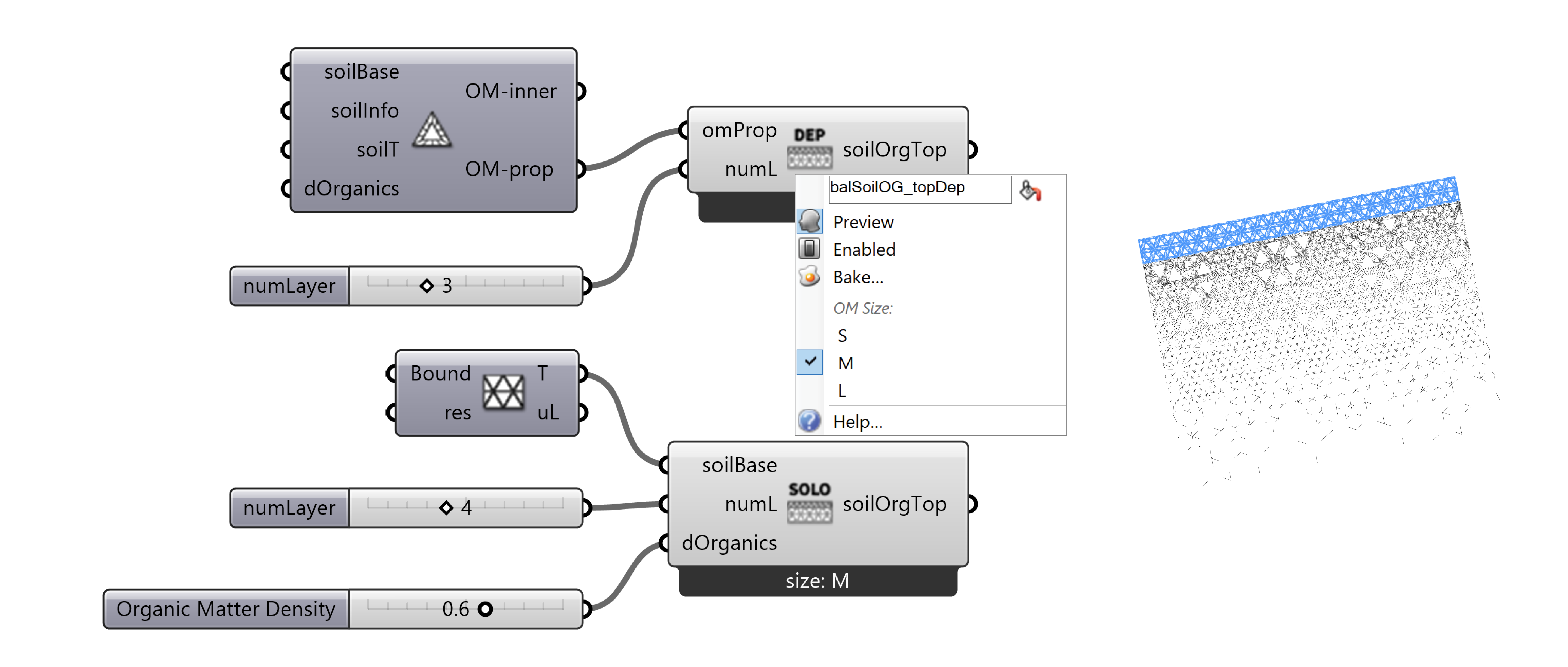
dependent version
The dependent version (top) use output of from the component Soil Interior Organic Matter, so that the density of the two parts match automatically.
| Parameter | Abbreviation | I/O | Optional | Explanation |
|---|---|---|---|---|
OM Property |
omProp |
No | The organic matter property, using output from the Soil Interior Organic Matter component. | |
numLayer |
numL |
Yes | # of layers in the surface organic matter. | |
Organic Matter Top |
soilOrgTop |
A diagram representing the organic matter on the soil surface. |
independent version
The independent version (bottom) use the output from the component Soil Base, allowing the user to freely define the parameters.
| Parameter | Abbreviation | I/O | Optional | Explanation |
|---|---|---|---|---|
Soil Base |
soilBase |
No | The soil base, using output from the Soil Base component. | |
numLayer |
numL |
Yes | # of layers in the surface organic matter. | |
Organic Matter Density |
dOrganics |
Yes | Density of organic matter [0, 1]. |
|
Organic Matter Top |
soilOrgTop |
A diagram representing the organic matter on the soil surface. |
- Context Menu: This component provides an additional option in the right-click menu for both the dependent version and the independent version. It allows to choose from different sizes of the surface organic matter diagram for different purposes.
| Parameter | Abbreviation | I/O | Options | Explanation |
|---|---|---|---|---|
OM Size |
OM Size |
S/M/L | Size of organic matter triangles: S - small, M - middle, L - large. |
Demo File
The Soil Demo (.gh file) is a grasshopper file that contains example definitions for Soil diagram generation. Please see the documentation section for more details.
-
Soil Science Division Staff. 2017. Soil survey manual. C. Ditzler, K. Scheffe, and H.C. Monger (eds.). USDA Handbook 18. Government Printing Office, Washington, D.C. ↩
-
Yuksel, C. (2015) ‘Sample elimination for generating Poisson disk sample sets’, Computer Graphics Forum, 34(2), pp. 25–32. doi:10.1111/cgf.12538. ↩
-
Understanding Soil Compaction – Field Crop News. (n.d.). Field Crop News - Ontario Ministry of Agriculture, Food and Rural Affairs in Partnership With the University of Guelph. https://fieldcropnews.com/understanding-soil-compaction/# ↩